Heater with temperature controller for solar wax melters
Heater with temperature controller for solar wax melters
Materialliste
Description
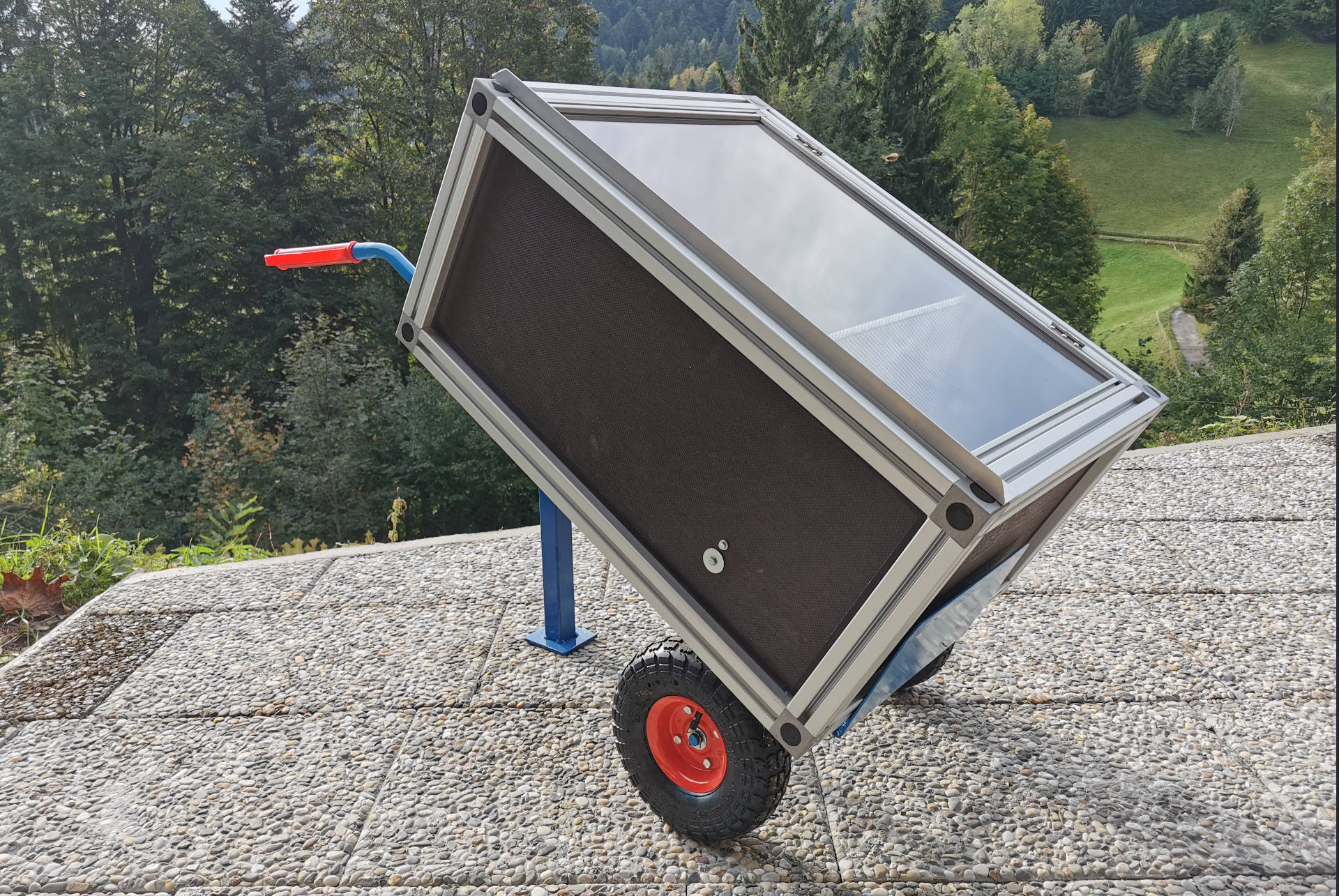
In summer, a solar wax melter is the best way for me to melt old honeycombs immediately. Since bees are often foraging during this time, it's difficult to use a steam wax melter or steam wax extractor. Furthermore, these devices are often only worthwhile for large quantities of old honeycombs. The effort required to clean the devices is too great to melt just a few combs, and storing the combs for a longer period until a larger quantity is collected is impossible due to wax moths.
To install the heater, I used my solar wax melter, which unfortunately only generated sufficient heat on extremely hot summer days. The solar wax melter has space for 10 combs and, thanks to its mounting on a handcart, is mobile despite its size. The only disadvantage of this model is that the outside temperature must be very high for the old combs to melt properly and for the beeswax to flow completely into the tub.
So I came up with the idea that an additional heater could solve this problem, and I quickly considered how to implement simple temperature regulation. Since I already had a lot of experience with the Particle microcontroller boards from the beehive scales, I immediately set up a test setup and wrote the appropriate program.
The heating element requires 220V, which is why I also used the FeatherWing Power Relay from Adafruit and the Particle FeatherWing Tripler for easy wiring. The DHT22 has served me well as a temperature sensor many times, and there's also a suitable program library for it.
The principle of the circuit and the program are incredibly simple. The temperature sensor measures the temperature – if it's below 60°C, the heating element is switched on via the power relay. As soon as the temperature rises above this value, the heating element is switched off again. Since the temperature control doesn't need to be very precise, it's perfectly sufficient to measure the temperature every minute. To show the temperature and humidity levels in the solar wax melter, these values are transmitted to the Particle Console.
Fritzing - circuit diagram
Fritzing - plug-in board:
Installation and programming
To regulate the temperature of the solar wax melter, I use a Wi-Fi microcontroller board from Particle with the FeatherWing design. It doesn't really matter whether I use a Particle Argon or a Photon 2. In principle, a Boron with a 2G/3G network connection could also be used. To use one of these boards, you must first complete the setup process. This involves loading the latest firmware version onto the board and establishing a network connection. You then need to assign the board to a product or create a new product. At the end of the setup, the device appears in the Particle console. Here you can check the device's network status and the state of variables, which must first be set in the program code.
There are two ways to write, compile, and transfer the program code to the Particle device. We can either create the program directly in Particle's Web IDE or install the Particle Workbench in Visual Studio Code. Using the Web IDE is certainly the easiest and fastest way to create a program and transfer it to a Particle device. I would therefore recommend using the Web IDE for this simple program example.
The program code can be divided into three sections. The first section involves incorporating program libraries and defining variables. This is followed by the setup code. This is only executed once and, in this case, involves registering variables that can be accessed in the Particle console in the future.
The third section of the program consists of a loop function that is executed repeatedly. Here, a Wi-Fi connection is first established, then the device is connected to the cloud. The temperature and humidity of the DHT22 sensor are then determined and transmitted to the Particle Cloud. The last section is a simple if statement that turns the heating element on when the temperature falls below 60°C and turns it off when the value rises above this value.
I think the program still has a lot of room for improvement, but it should be sufficient to demonstrate the basic principle of temperature control.
/*
* Project HeatController
* Author: Dieter Metzler
* Date: 03.05.2024
* For comprehensive documentation and examples, please visit:
* https://docs.particle.io/firmware/best-practices/firmware-template/
*/
// Include Particle Device OS APIs
#include "Particle.h"
#include "PietteTech_DHT.h"
#define DHTTYPE DHT22 // Sensor type DHT11/21/22/AM2301/AM2302
#define DHTPIN A0 // Digital pin for communications
// Let Device OS manage the connection to the Particle Cloud
SYSTEM_MODE(SEMI_AUTOMATIC);
//********************************************************************
// Automatically mirror the onboard RGB LED to an external RGB LED
// No additional code needed in setup() or loop()
//Since 0.6.1 Allows a set of PWM pins to mirror the functionality of the on-board RGB LED.
STARTUP(RGB.mirrorTo(D4, D5, D6));
// Show system, cloud connectivity, and application logs over USB
// View logs with CLI using 'particle serial monitor --follow'
SerialLogHandler logHandler;
// We define MY_LED to be the LED that we want to blink.
//
// In this tutorial, we're using the blue D7 LED (next to D7 on the Photon
// and Electron, and next to the USB connector on the Argon and Boron).
const pin_t Heater = D7;
// The following line is optional, but recommended in most firmware.
// allows your code to run before the cloud is connected. In this case,
// it will begin blinking almost immediately instead of waiting until
// breathing cyan,
SYSTEM_THREAD(ENABLED);
// Lib instantiate
PietteTech_DHT DHT(DHTPIN, DHTTYPE);
double tempC = 0;
double hum = 0;
double vol = 0;
float temperature;
float humidity;
float voltage;
// The setup() method is called once when the device boots.
void setup() {
Serial.begin(9600);
Particle.variable("temp", tempC);
Particle.variable("hum", hum);
Particle.variable("vol", vol);
DHT.begin();
// In order to set a pin, you must tell Device OS that the pin is
// an OUTPUT pin. This is often done from setup() since you only need
// to do it once.
pinMode(Heater, OUTPUT);
}
// The loop() method is called frequently.
void loop() {
//WiFi.off(); //Turning off the WiFi module will force it to go through a full re-connect to the WiFi network the next time it is turned on.
delay(500);
WiFi.on(); //Turns on the WiFi module. Useful when you've turned it off, and you changed your mind.
Serial.println("WiFi on...");
delay(500);
WiFi.connect(); // This command turns on the WiFi Modem and tells it to connect to the WiFi network.
Particle.connect(); //Connects the device to the Cloud. This will automatically activate the cellular connection and attempt to connect to the Particle cloud if the device is not already connected to the cloud.
Serial.print(": Retrieving information from sensor: ");
Serial.print("Read sensor: ");
int result = DHT.acquireAndWait(1000); // wait up to 1 sec (default indefinitely)
switch (result) {
case DHTLIB_OK:
Serial.println("OK");
break;
case DHTLIB_ERROR_CHECKSUM:
Serial.println("Error\n\r\tChecksum error");
break;
case DHTLIB_ERROR_ISR_TIMEOUT:
Serial.println("Error\n\r\tISR time out error");
break;
case DHTLIB_ERROR_RESPONSE_TIMEOUT:
Serial.println("Error\n\r\tResponse time out error");
break;
case DHTLIB_ERROR_DATA_TIMEOUT:
Serial.println("Error\n\r\tData time out error");
break;
case DHTLIB_ERROR_ACQUIRING:
Serial.println("Error\n\r\tAcquiring");
break;
case DHTLIB_ERROR_DELTA:
Serial.println("Error\n\r\tDelta time to small");
break;
case DHTLIB_ERROR_NOTSTARTED:
Serial.println("Error\n\r\tNot started");
break;
default:
Serial.println("Unknown error");
break;
}
Serial.print("Humidity (%): ");
Serial.println(DHT.getHumidity(), 2);
humidity = DHT.getHumidity();
hum = humidity;
Serial.println("Humidity: " + String(humidity));
Serial.print("Temperature (oC): ");
Serial.println(DHT.getCelsius(), 2);
temperature = DHT.getCelsius();
tempC = temperature;
Serial.println("Temperature: " + String(temperature));
voltage = analogRead(BATT) * 0.0011224;
vol = voltage;
Serial.println("Voltage: " + String(voltage));
if (temperature <= 60) {
// Turn on the LED
digitalWrite(Heater, HIGH);
} else {
// Turn it off
digitalWrite(Heater, LOW);
}
delay(60000);
}
Hive stand
Hive stand
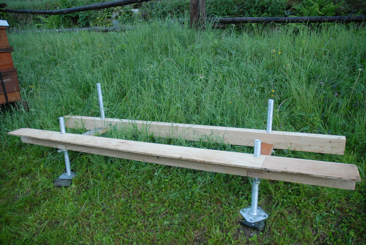
With the 4Bees hive stand, setting up bee colonies is child's play. The eight parts can be assembled without tools and can be completed in less than five minutes. The adjustable frame feet allow the hive stand to be adapted to any terrain.
Materialliste
Description
With the 4Bees hive stand, setting up bee colonies is child's play. The eight parts can be assembled without tools and can be completed in less than five minutes. The adjustable frame feet allow the hive stand to be adapted to any terrain. The beekeeper can easily raise the bee colonies to the desired working height. The quick and uncomplicated assembly is a major advantage, especially for migratory beekeepers. Home beekeepers will also enjoy this hive stand.
Assembly instructions
I will not use any measurements for the assembly instructions for the hive stand, as it can be easily built for the desired number of colonies and the corresponding hive size. The length of the support beams is calculated from the number of colonies times the hive width, plus approximately 3 cm of reserve per colony. The length of the cross planks corresponds to the hive length plus approximately 10 cm for mounting the landing board. For the cross planks, I use wood that is 10 cm wide and 4 cm thick. The frame legs should be 50 cm long so that the hive stand can be leveled even on slopes.
To give the hive stand sufficient stability, grooves are milled into the support beams for the cross planks. I determine the center of the groove by measuring the width of one colony plus 5 cm from the edge of the support beam. This is also the center of the hole for the frame leg. The diameter of the hole is 40 mm.
The hive stand can now be assembled in just a few steps and without any tools. However, if you want to level the stand perfectly, you'll need a spirit level.
Liebig High bottom board
Liebig High bottom board
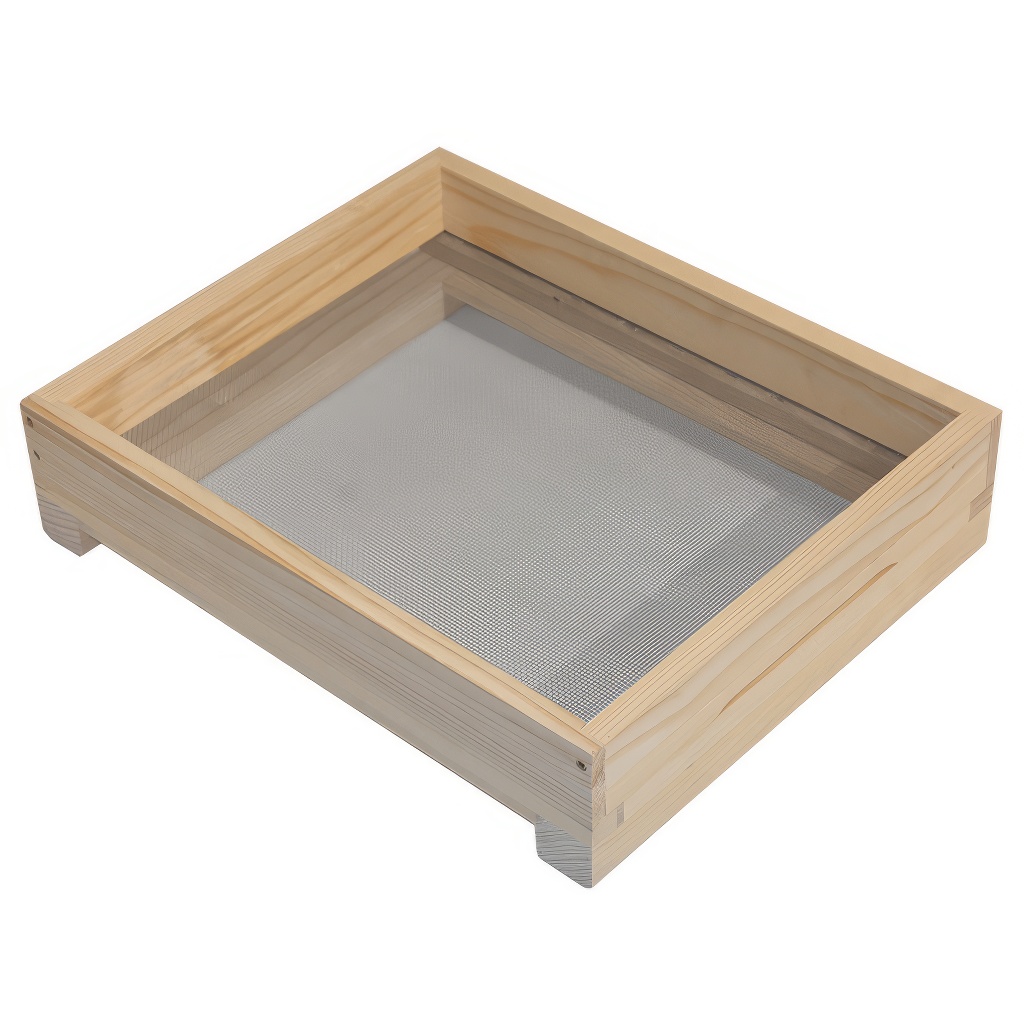
Bee hive bottoms are usually somewhat complex in design and require some craftsmanship. The Liebig high bottom is relatively easy to build and only requires straight cuts.
Material list:
Upper frame:
2x 52 cm x 8 cm x 2 cm
1x 38 cm x 8 cm x 2cm
2 x 38 cm x 5 cm 2 cm
1 x 38 cm x 3 cm x 2 cm
2x blocks ca. 3,5 cm x 3,5 cm x 2,5 cm
Lower frame:
2x 52 cm x 2,5 cm x 2 cm
1x 38,5 cm x 5 cm x 2 cm
2x 42 cm x 8 cm x 2cm
Stainless steel wire mesh 40 cm x 48 cm (2.5 mm mesh size; 0.5 mm wire thickness)
Entrance reducer:
1x 37,6 cm x 2,8 cm x 2 cm
2 x 12 cm x 2,8 cm x 1 cm
Monitoring board
Hardboard 4 mm, coated white: 47 cm x 37 cm
1 x 38,3 cm x 0.9 cm x 2cm
Work steps:
All necessary boards are planed to a thickness of 2 cm and milled to the dimensions specified above. The hardboard is best purchased in the appropriate size from a hardware store. The wire mesh is available at any beekeeping supply store.
The 52 cm long side panels are screwed to the 8 cm wide and 1 cm wide sections to form a frame. The second 5 cm wide board is screwed flush to the frame at a 90° angle at the front (5 cm board). The 3 cm wide board is screwed crosswise into the frame at the same height at the back. These two boards form the support for the construction barrier.
For the lower frame, the two side strips are milled into an L-shaped profile. 8 mm are milled out in width and 1.2 cm in height. The 38.5 cm long board is milled out on both ends of the counterpart. To ensure the two frames are connected evenly, a 2 mm and 1 cm wide recess must be milled into the three parts of the lower frame for the wire mesh. Now the two side parts can be glued and screwed to the front part. To reinforce the frame, the 8 cm wide feet are mounted as cross braces. The wire mesh is then stapled to the lower frame.
The upper and lower frames can now be connected.
The diaper consists of a white-coated hardboard to which the strip is stapled. A 30 mm screw is screwed into the strip for easy removal.
All exterior parts are painted with a water-resistant paint.
Frame feeder
Frame feeder
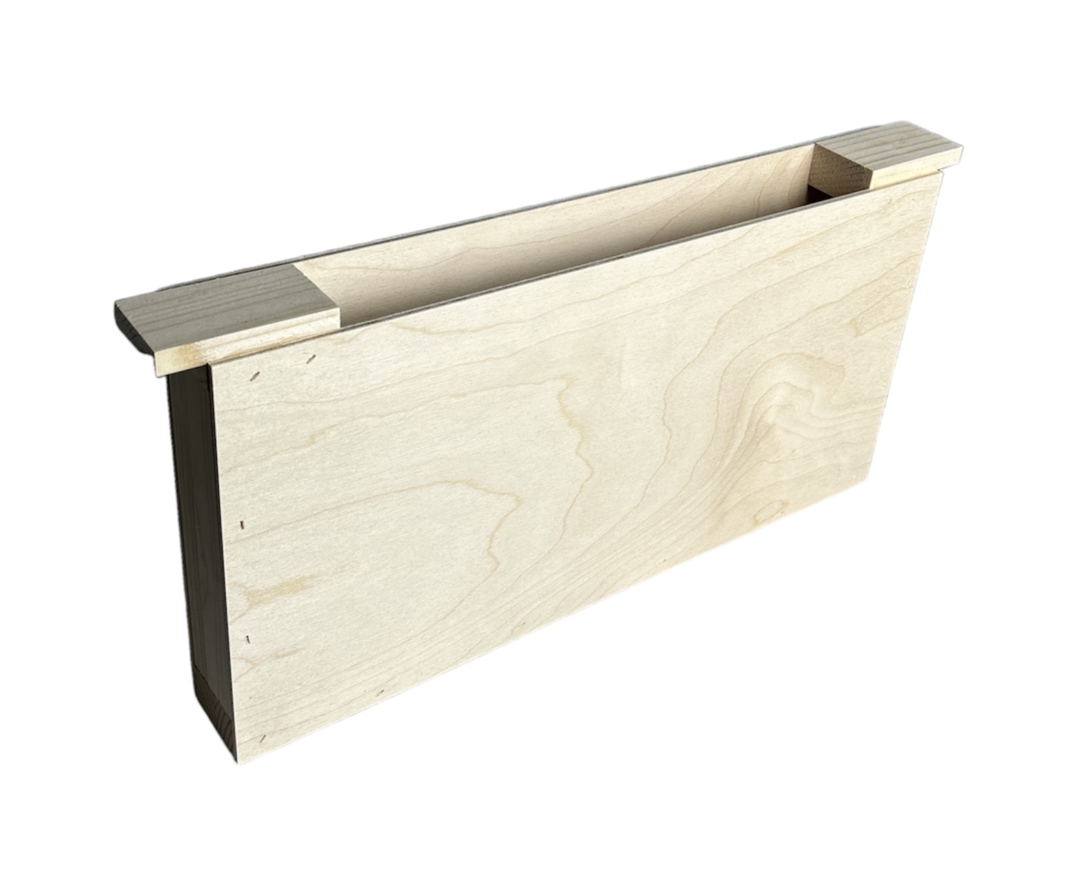
The frame feeder is particularly suitable for feeding nucs. It is often also used as a divider to restrict the space of young colonies.
Wooden parts
Strip 1 cm
1x 42 cm x 3 cm
2x 20 cm x 3 cm
2x 11,5 cm x 3 cm
Blocks 2,5 cm
2 x 8 cm x 3 cm
4 mm hardboard or plywood
1x 42 cm x 22 cm
1x 42 cm x 21 cm
Work steps
A board is planed to a thickness of 3 cm and then milled into strips 1 cm and 2.5 cm wide. All strips are then cut to the appropriate lengths.
The hardboard is easiest to cut to the required size at a hardware store.
The 11.5 cm long strips are tacked flush to the blocks on one side. The 20 cm long side pieces are nailed to the blocks on the protruding side. The 42 cm long strip then connects the side pieces to form a frame.
The hardboard is now glued and stapled to the frame with the rough side facing inward.
Liebig Zander hive
Liebig Zander hive
The Liebig Zander hive is a widely used hive frame. It is available in various heights as a full frame, flat frame, and half frame. Since all parts require only straight cuts, it is very easy to manufacture.
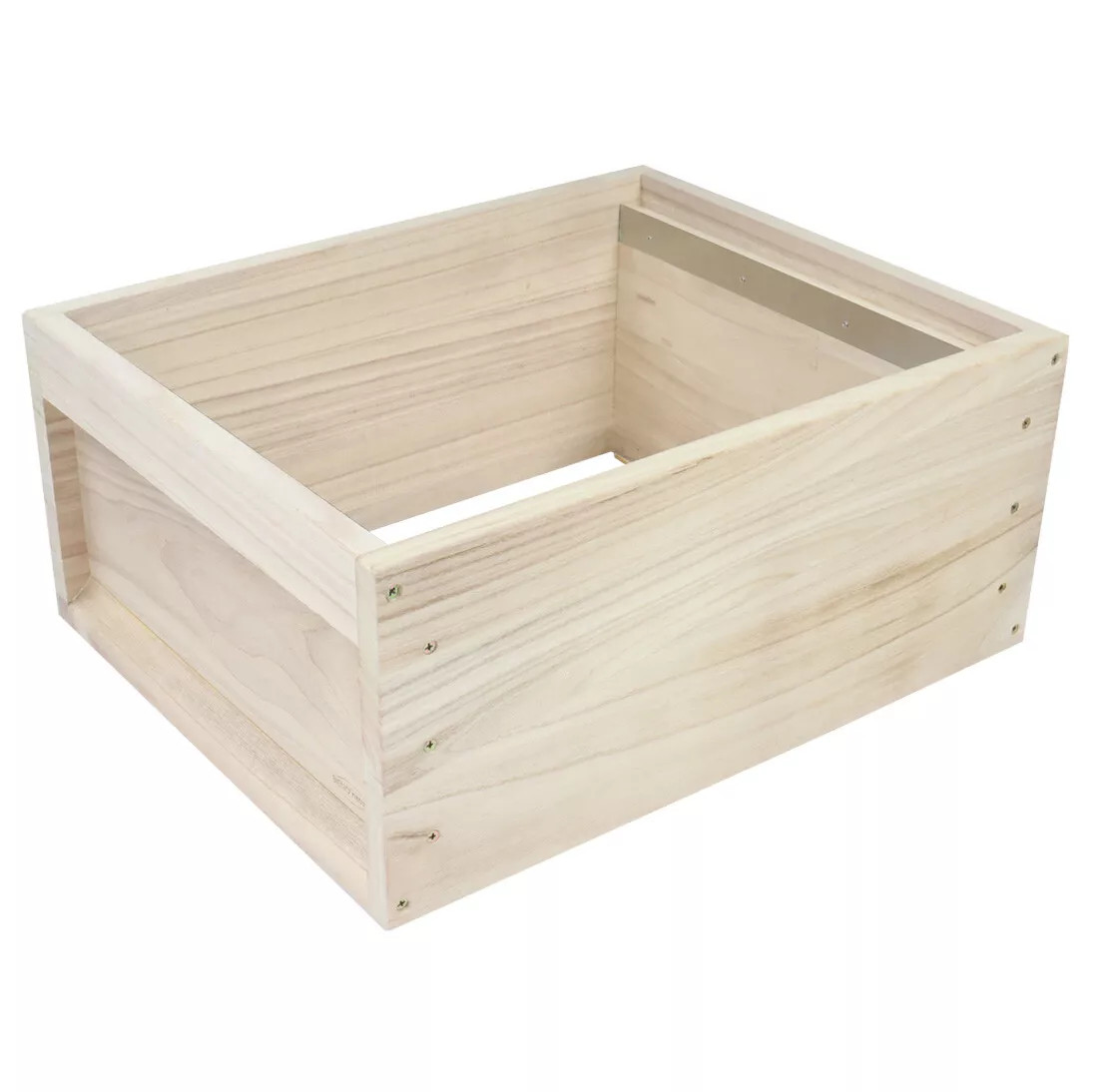
The wall thickness of the Liebig Zander hive is 20 mm. Therefore, all boards are first planed to 20 mm. Then all wooden parts are milled. One frame consists of 8 wooden parts plus 2 hardwood sliding strips.
Full frame
| Side board | 2x | 520 x 227 | 20 mm |
| End board | 2x | 380 x 205 | 20 mm |
| Handle bar | 2x | 380 x 60 | 20 mm |
| Support bar | 2x | 380 x 30 | 20 mm |
| Slide bar | 2x | 376 x 18 | 5 mm (Hardwood) |
Flat frame
| Side board | 2x | 520 x 170 | 20 mm |
| End board | 2x | 380 x 145 | 20 mm |
| Handle bar | 2x | 380 x 60 | 20 mm |
| Support bar | 2x | 380 x 30 | 20 mm |
| Slide bar | 2x | 376 x 18 | 5 mm (Hardwood) |
Half Frame
| Side board | 2x | 520 x 120 | 20 mm |
| End board | 2x | 380 x 100 | 20 mm |
| Handle bar | 2x | 380 x 60 | 20 mm |
| Support bar | 2x | 380 x 30 | 20 mm |
| Slide bar | 2x | 376 x 18 | 5 mm (Hardwood) |
Once all parts have been milled to the required length and width, they can now be glued and screwed together. It's best to pre-screw four screws into each side board. Then, glue and screw the handle bar and the support bar. Next, glue and screw the end boards and finally the second side board.
Now, the hives can be painted in the desired color. To prevent the honeycombs from sticking together too tightly, two rails are installed to support the honeycombs.
Liebig - Split hive bottom board
Liebig - Split hive bottom board
The Liebig - Split hive bottom board is a low, special floor that divides a hive into three equal-sized chambers with two slats. Two slats, which are hung into the hive, and the groove in the slats of the floor create a bee-tight separation.
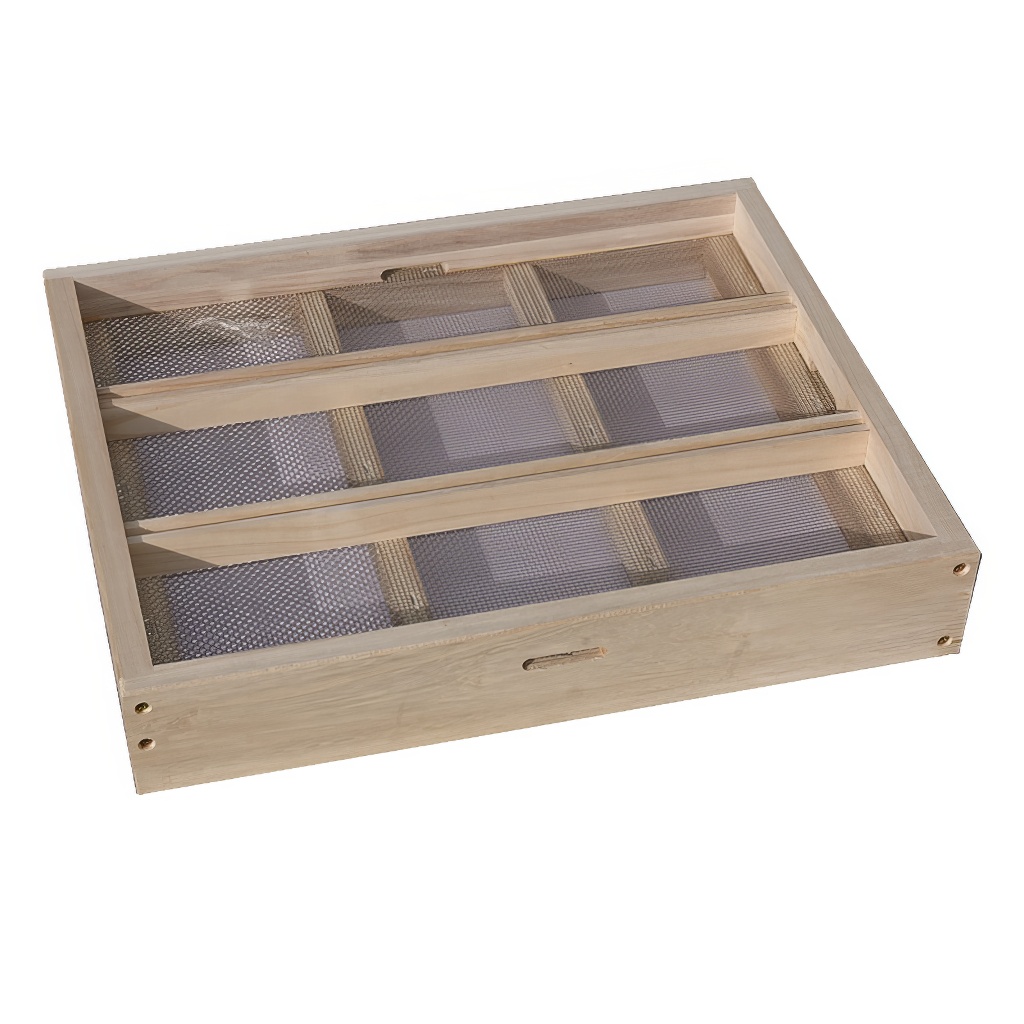
Liebig - Split hive bottom board
The split hive bottom board consists of 12 wooden parts, a grid and 12 screws (40 x 3.5) for the floor, 3 wooden parts and one screw (30 x 3.5) for the diaper, and 2 plywood sheets. A planer, a circular saw, a cordless screwdriver, a stapler, and tin snips are required to manufacture the parts and assemble them.
Parts:
Frame above:
2x 38 cm x 4 cm x 2cm
2x 52 cm x 4 cm x 2 cm
Frame below:
2x 52 cm x 5 cm x 2 cm
1x 38 cm x 5 cm x 2 cm
1x 38 cm x 1,7 cm x 2 cm
Cross and longitudinal strips:
2x 48 cm x 3,5 cm x 2 cm
1x 38 cm x 2 cm x 2 cm
1x 38 cm x 1,5 cm x 2 cm
Mesh (stainless steel wire mesh: 2.5 mm mesh size, 0.5 mm wire thickness):
50 cm x 40 cm
Monitoring board:
37,5 cm x 1,7 cm x 2 cm
37,5 cm x 1,5 cm x 1,5 cm
Hardboard 4 mm coated white: 50 cm x 40 cm
Separation board:
Plywood board 4 mm: 48 cm x 24 cm
Arbeitsschritte:Work steps:
The required boards are planed to a thickness of 2 cm. All parts are milled to the appropriate dimensions. The wire mesh is cut with tin snips.
In die beiden Längsleisten (48 cm x 3,5 cm) wird eine 1,3 cm tiefe und 1cm breite Nut gefräst.
In die Seitenteile (52 cm x 5 cm) des unteren Rahmens werden sie 7 mm Höhe jeweils eine Nut mit 7 mm Breite für die Windel gefräst. In die obere Seite aller Teile des unteren Rahmens wird in 1 cm breite und 2 mm tiefe Kerbe gefräst damit das Drahtgitter etwas versenkt werden kann.
Der ober Rahmen mit den zwei Längsleisten und der untere Rahmen mit zwei Querleisten können jetzt verleimt und zusammengeschraubt werden.
Auf den unteren Rahmen wird das Drahtgitter getackert.
Oberer und unterer Rahmen können jetzt verleimt werden.
A 1.3 cm deep and 1 cm wide groove is milled into the two longitudinal strips (48 cm x 3.5 cm).
A 7 mm wide groove is milled into each of the side panels (52 cm x 5 cm) of the lower frame, 7 mm high, for the diaper. A 1 cm wide and 2 mm deep notch is milled into the upper side of all panels of the lower frame so that the wire mesh can be slightly recessed.
The upper frame with the two longitudinal strips and the lower frame with two cross strips can now be glued and screwed together.
The wire mesh is stapled to the lower frame.
The upper and lower frames can now be glued together.
Monitoring Board
The two strips are stapled to the center of the hardboard at the front and back. A screw is screwed into the center of the wider strip to make it easier to remove the monitoring board.
Seperation Board
From a plywood sheet (48 cm x 24 cm) 2.2 cm wide strips are milled away on the sides so that 2 cm remain for the ears.
BeeMobil - The mobile bee house
BeeMobil - The mobile bee house
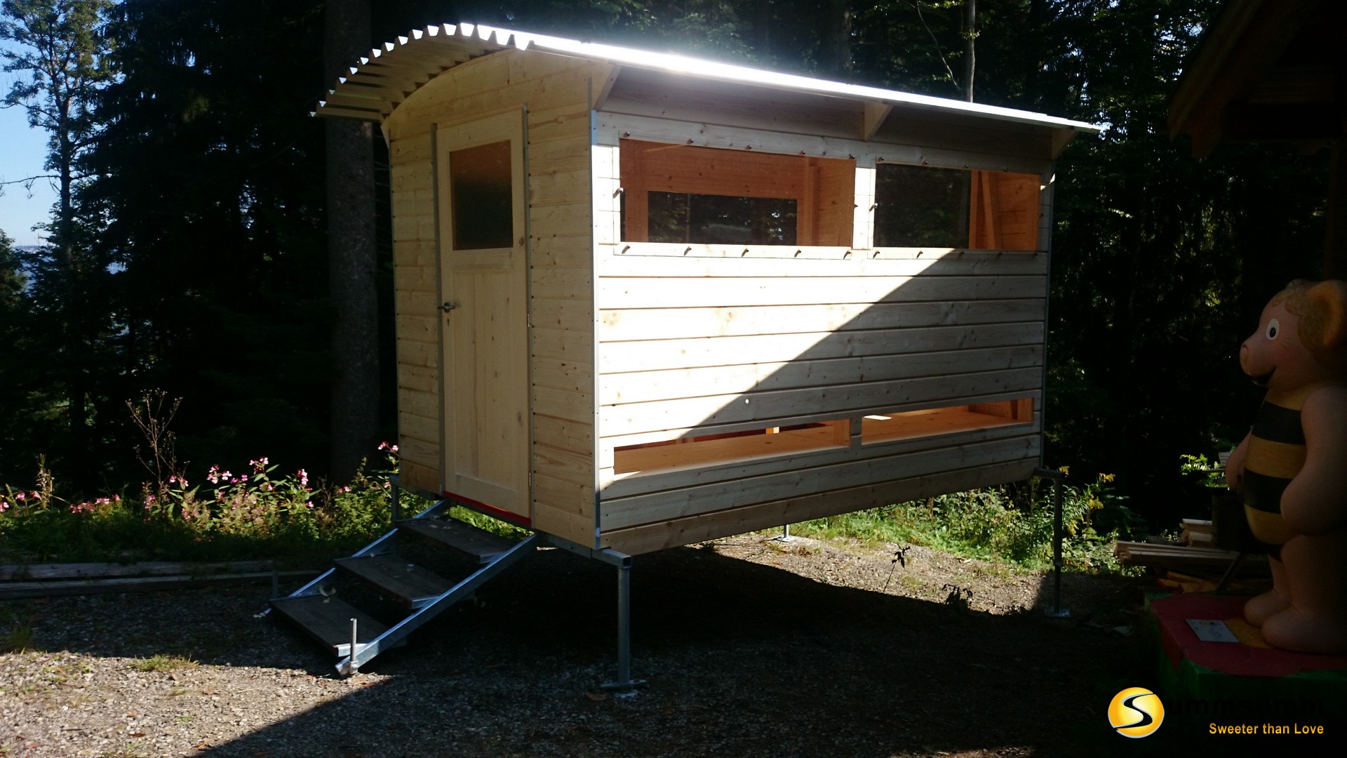
The BeeMobil is a mobile bee house that offers space for 13 bee colonies or 25 nucs and can be easily moved to a new location using a car trailer.

Materialliste
Moving bee colonies can significantly increase honey yields by transporting the bees to where they can collect nectar. However, moving the colonies is very labor-intensive and usually requires an assistant to help carry the hives. Since the bees have to be moved in the early morning hours, it is often difficult to find someone to help.
The BeeMobil is therefore the ideal solution for any migratory beekeeper. It can be lifted by one person using an off-road jack and loaded onto a trailer. All colonies remain in the hive. Only the entrances need to be closed and the colonies secured with straps to prevent them from shifting.
Assembly instructions
Substructure:
The two long rectangular shaped tubes are welded to the two shorter ones to form a frame (instructional video on welding a frame). For reinforcement, the third shaped tube is welded to the frame in the middle. A 10 mm diameter hole is drilled in the center of each of the four short square shaped tubes, into which an M10 nut is then welded. These are used to secure the uprights using the M10 x 20 mm hexagon bolts. The short square shaped tubes can now also be welded to the frame.
For each of the four uprights, a round shaped tube is welded to a square shaped tube at a 90° angle. The frame and the four uprights are then galvanized with the stair components.
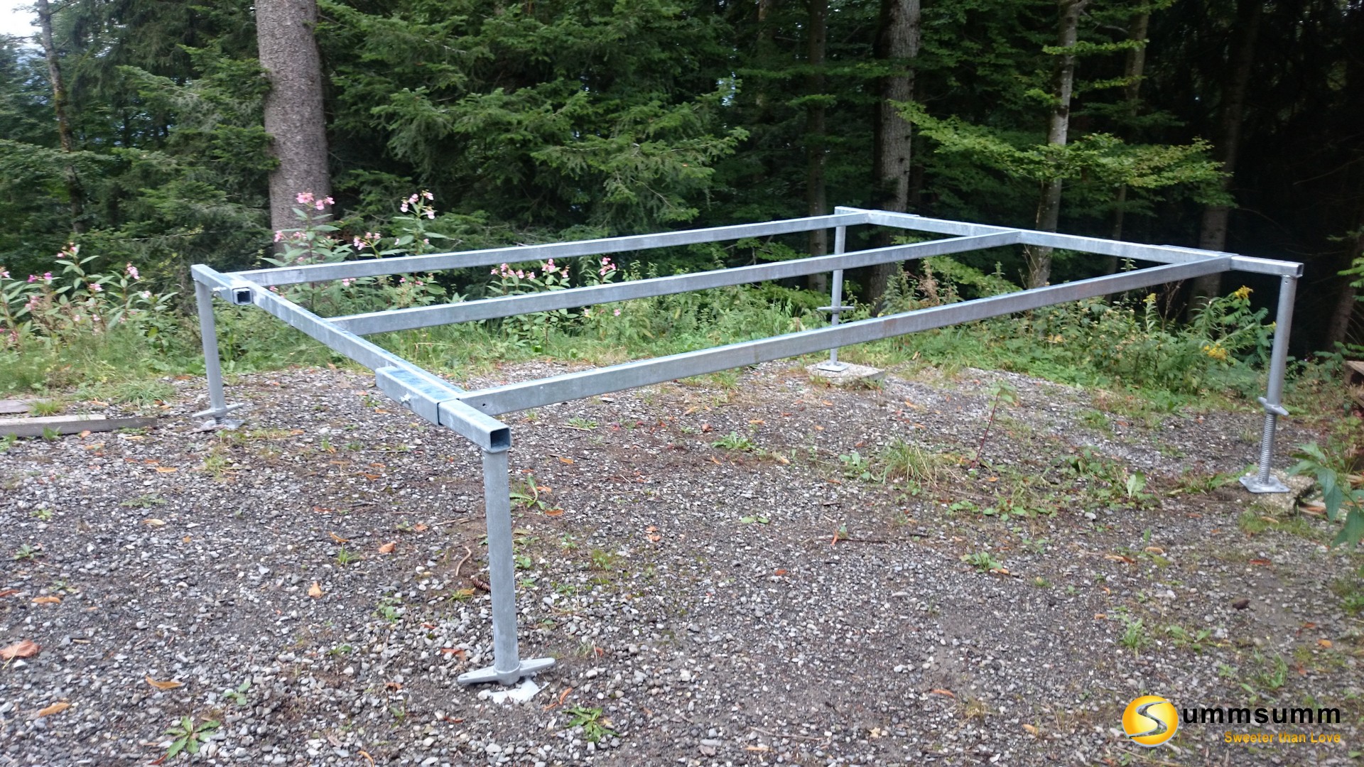
Stairs:
For the stairs, the short rectangular shaped tubes are welded to the U-profiles and two short square shaped tubes each. A 10 mm hole is drilled into each of the short shaped tubes, and an M10 nut is welded to it. This serves to secure the small uprights. For the small uprights, a short 20 mm diameter tube is welded at a right angle to the center of the 100 mm x 100 mm sheet. The stair components are then galvanized.
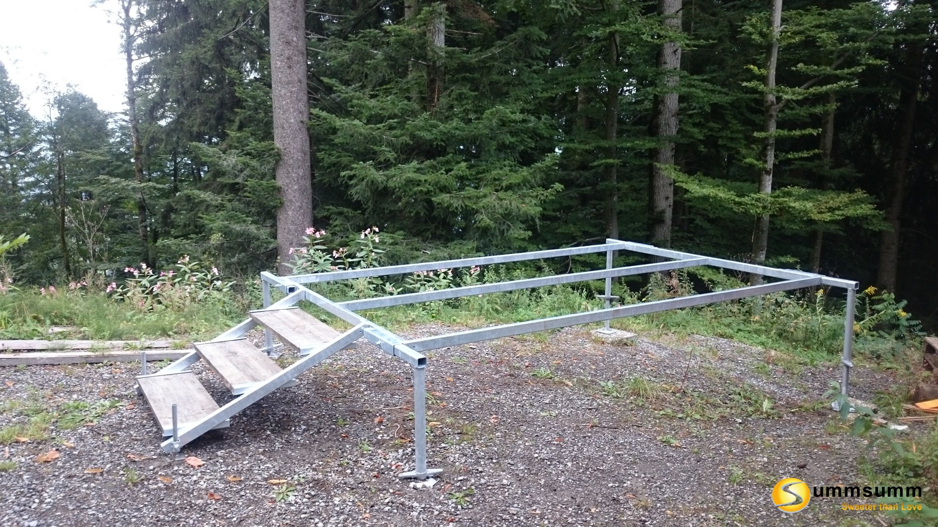
Floor:
For the floor, the 2 m long formwork panels are sawn to a length of 1.9 m. The first formwork panel is then fixed flush with the outer edge of the frame using two screw clamps. Two holes with a diameter of 5 mm are then drilled through the formwork panel and the steel frame on both sides and in the middle and then countersunk using a countersunk drill so that the countersunk screws can then be screwed in flush with the floor. First, however, threads must be turned in all holes using an M6 thread cutter. The formwork panel can now be screwed to the frame using 6 M6 countersunk screws. This is how all the formwork panels are screwed to the frame. The last one must of course be sawn to the remaining width.
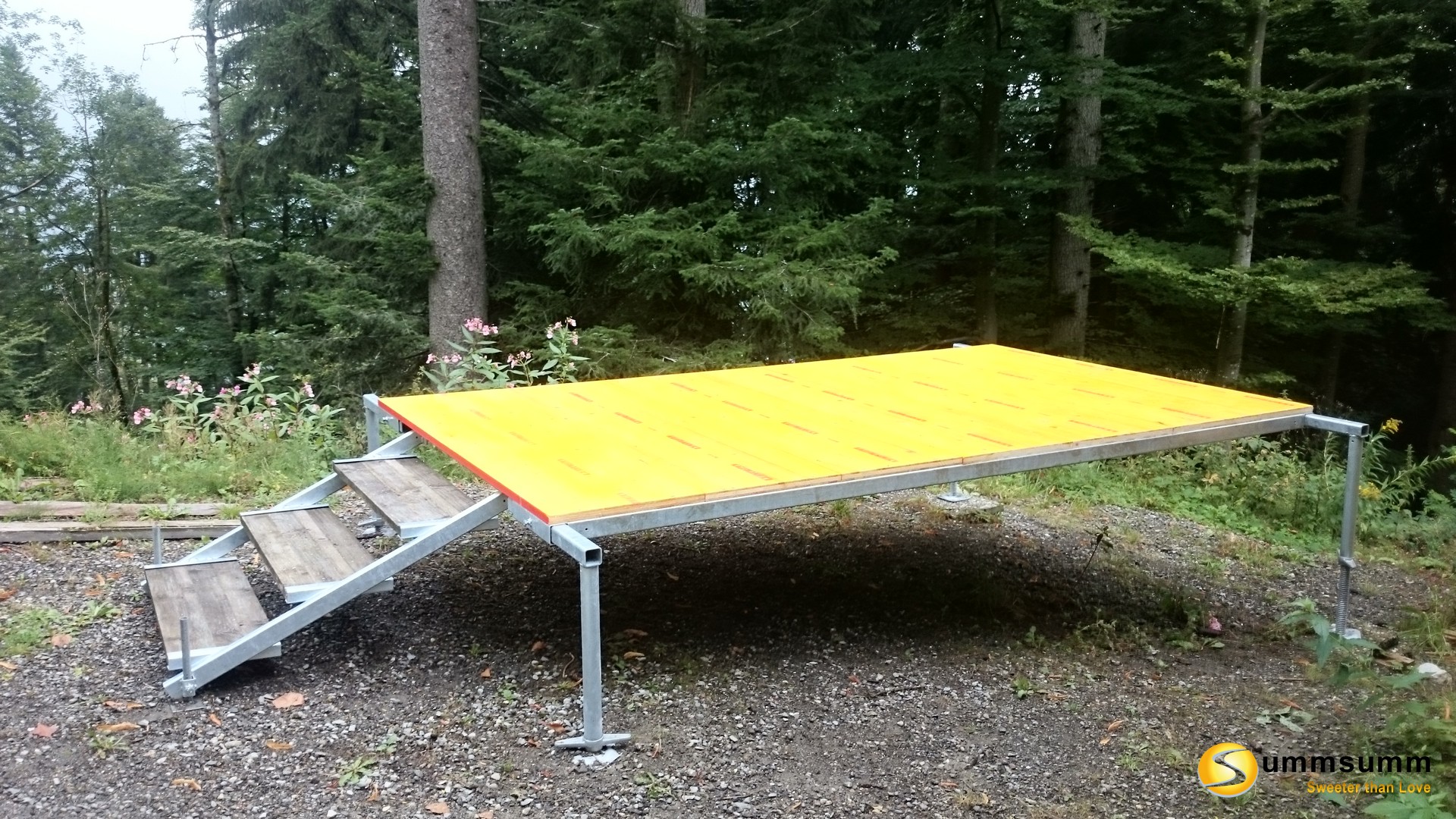
Side reinforcement:
The 4 m building boards are sawn to a length of 3.2 m. 6.5 cm squares are sawn out of the two bottom corners using a jigsaw. The building board is then fixed to the frame flush at the side edges and at the bottom edge using two screw clamps. A total of seven holes with a diameter of 10 mm are drilled at regular intervals through the center of the steel frame and the building board. To countersink the M10 cylinder head screws, each hole must be drilled about 10 mm deep using a 16 mm wood drill. The M10 cylinder head screws are now pushed through the building board and the steel frame and screwed tight with a washer and nut.
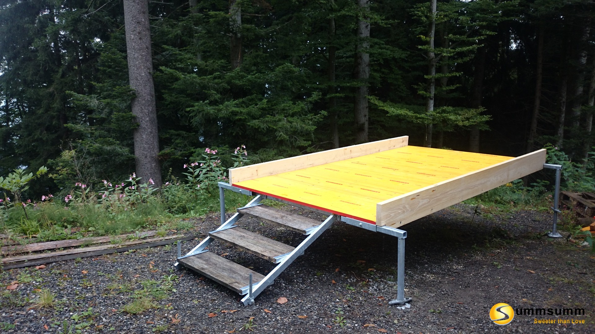
Body construction:
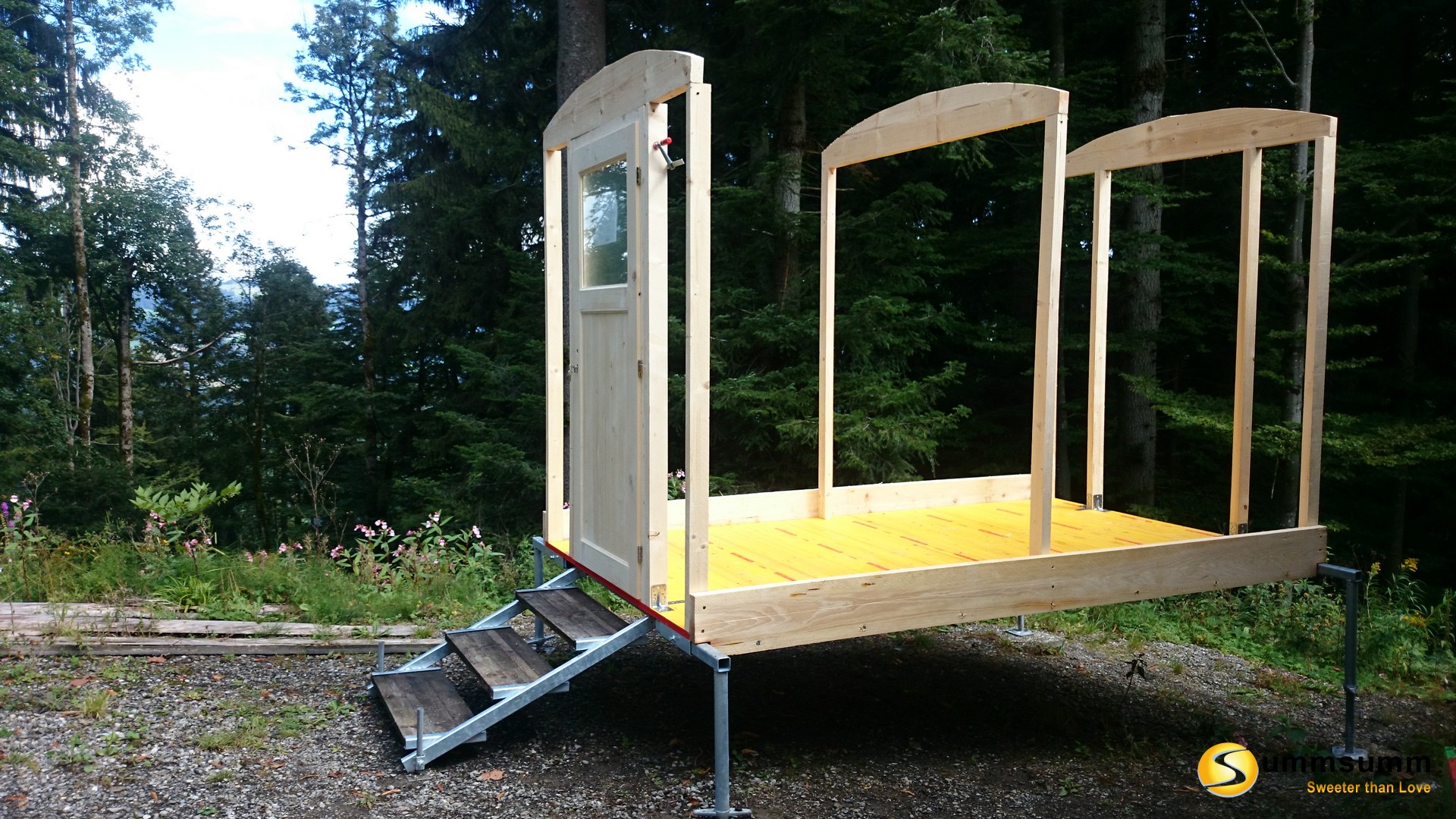
In the next step, 1.99 m high uprights are attached at right angles to the floor at all four corners and in the center using connecting brackets. Two additional uprights are also attached at the front and rear, spaced at the width of the door.
For the roof structure, two planks are sawn to 3 x 1.9 m and cut into an arch using a jigsaw or band saw. This arch is then connected to the uprights using 140 mm screws.
To increase lateral stability, two additional cross braces are inserted into the front and rear walls. (See image of walls.)
To achieve a height of 25 cm for the platform, the two side reinforcements are raised by 10 cm. For this purpose, a construction board is sawn to two 100 mm wide and 3.2 m long. 5 cm squares are sawn out on the top side flush with the edge posts, in the middle, and on both sides flush with the center posts. The cross battens for the platform are then inserted here.
All six posts are now reinforced with a second piece of structural timber so that the wainscoting for the walls can be attached directly.
Podium:
For the platform, we need 12 pieces of 55 cm square timber and 12 pieces of 18.5 cm square timber. These are sawn from the remaining construction timber. The 55 cm long pieces of square timber are sawn out on one side so that a tenon measuring 5 cm x 5 cm remains. These then fit exactly into the notches in the side reinforcement. The other end is connected to the 18.5 cm square timber using a 140 mm screw. This should create a slight slope towards the entrance hole. Now 20 mm boards or 27 mm 3-ply panels can be laid.
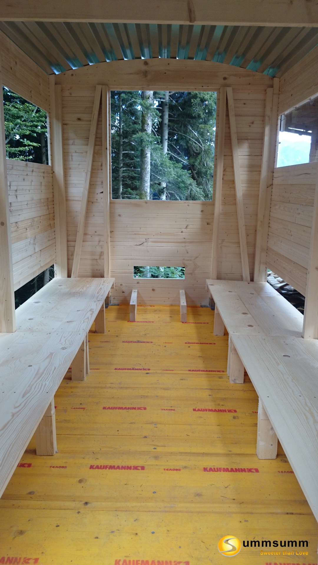
Walls:
To ensure the top and bottom of the structure are the same length, a 3.32 m long construction timber is first attached to both sides. 12 3.32 m long wainscoting boards are required on each side. The first wainscoting board is installed flush with the bottom edge of the frame. The entrance hole is cut out at a height of 15 cm on the third and fourth boards. After the tenth, three layers of 15 cm wide wainscoting boards are attached to the sides and in the middle. The eleventh board is cut out to create a window width of 44 cm. The last board then needs to be sawn to the appropriate width.
For the front, 28 wainscoting boards are needed, each 54 cm long, and two 2.03 m long, plus a scrap piece for the arch.
For the back, we saw 10 wainscoting boards to a length of 2.03 m and 12 to a length of 54 cm. For the third, we saw a 50 cm wide and 15 cm high entrance hole in the center, 26 cm from the ground. The hole for the window must be 94 cm x 94 cm and at a height of 1.03 m from the ground.
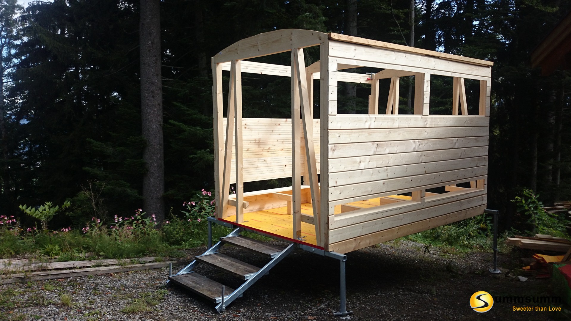
Door:
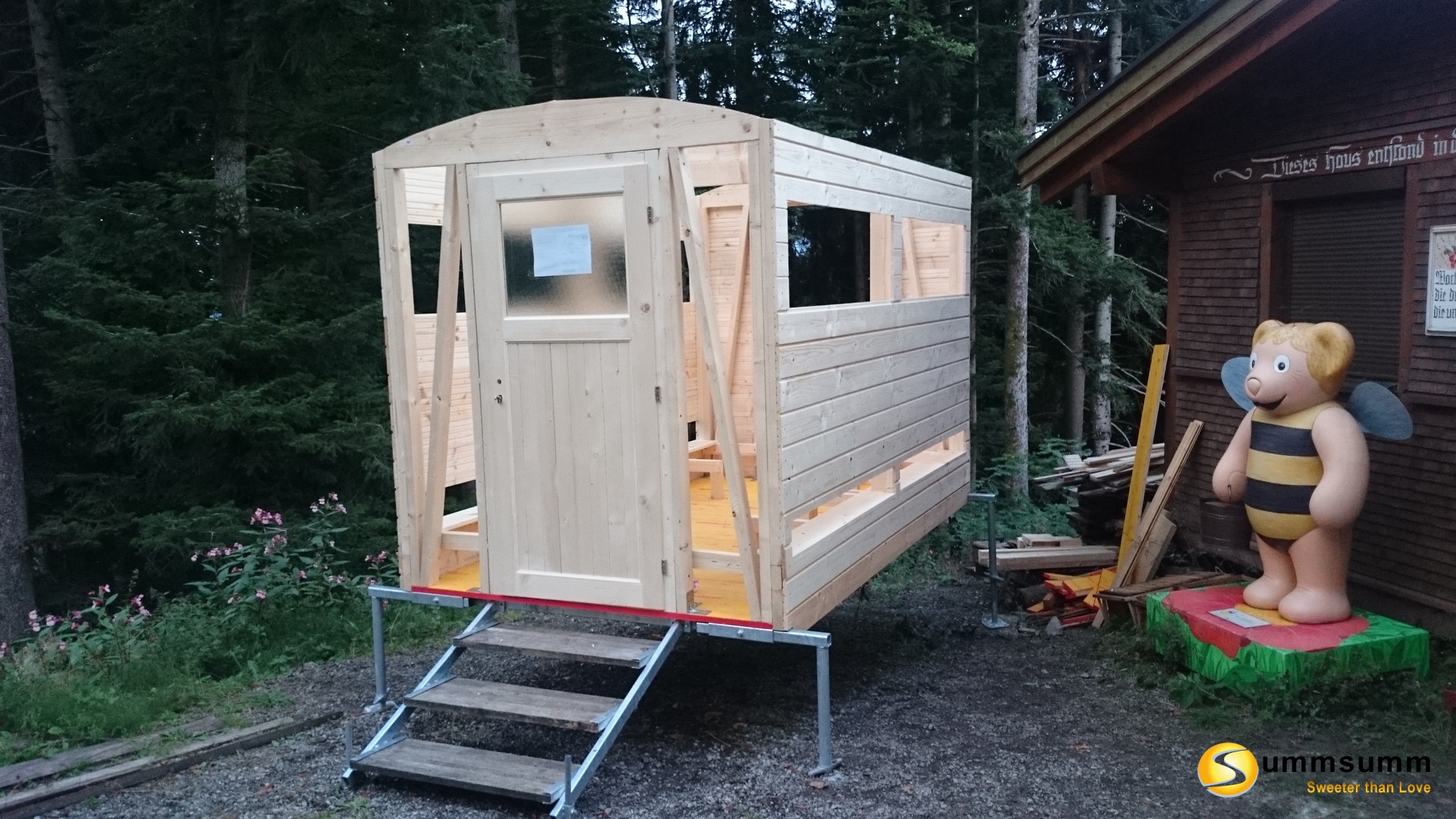
The door is inserted and screwed to the controls. It should have some space, as it can expand slightly due to moisture.
Roof:
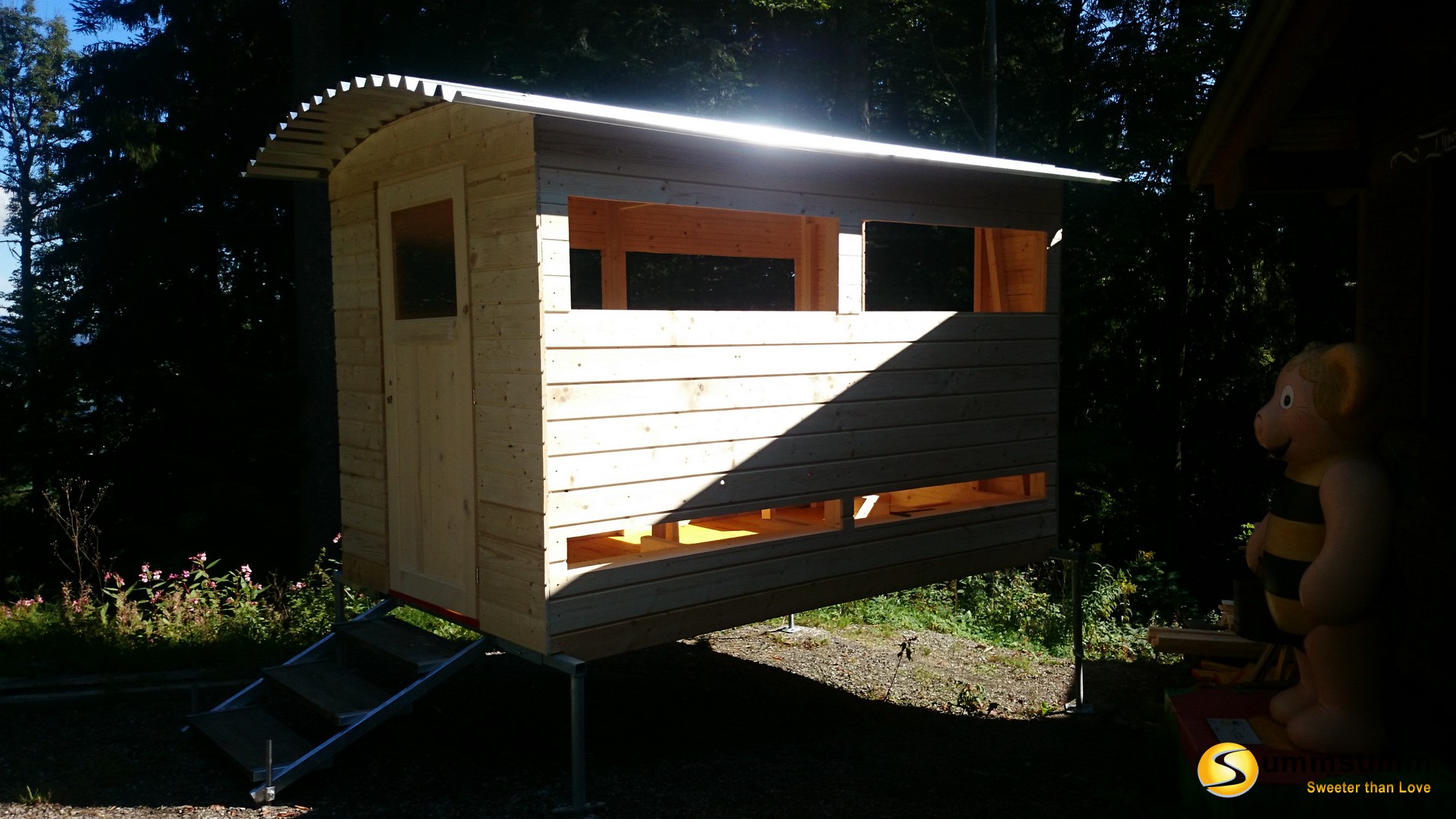
First, the middle panel is attached with three screws. The front canopy is slightly longer than the rear at 40 cm. Now, another panel can be slid underneath on each side and screwed in place.
Window:
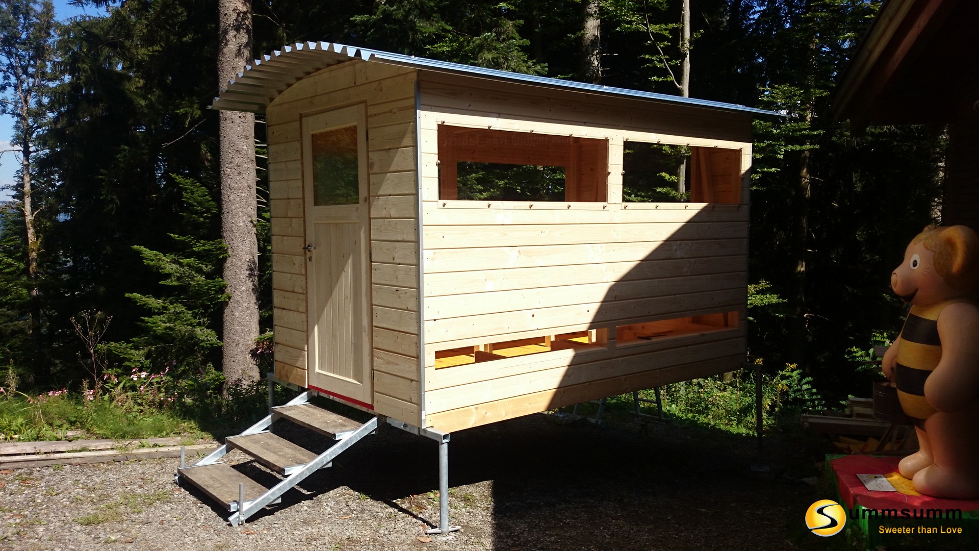
For the windows, 13 mm spacers are first sawn from the round bar and a 5 mm diameter hole is drilled. The windows are mounted with sheet metal screws.
Trim strips and roof reinforcement:
For added beauty, aluminum trim strips can be added to all four corners and the door frame. The side canopy is reinforced with wooden wedges.
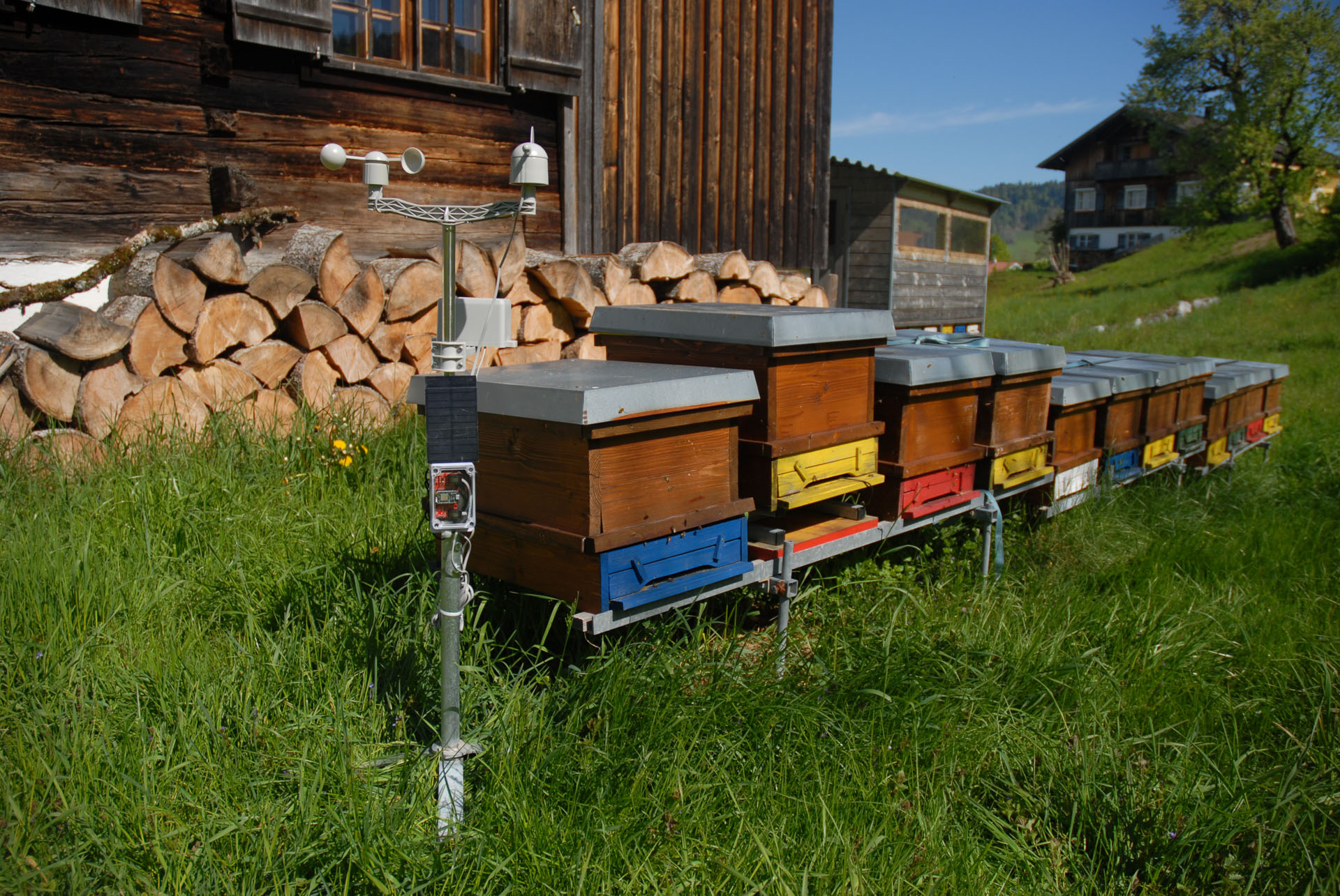
Weather station with the Particle Photon
Weather station with the Particle Photon
The weather station records all important weather data such as temperature, humidity, air pressure, wind direction, wind speed, rainfall and soil moisture around your apiary.
Materialliste
Structure and hardware
Weather sensors
The weather station uses the Weather Meter from SparkFun. This weather sensor includes three core components: wind speed, wind direction, and rainfall.
The rain gauge consists of a rocker with two self-emptying baskets, each with a capacity of 0.011 inches of rain. When a basket is full, a button is activated. This means that only the number of pulses per unit of time needs to be determined to determine the amount of rain.
The anemometer (wind speed meter) measures the number of revolutions. With each revolution, a switch is activated. At a wind speed of 1,492 MPH, the switch closes exactly once per second.
The wind direction is determined using a voltage that changes with the wind direction due to the combination of resistors within the sensor. Up to two switches can be activated simultaneously using magnets. This allows 16 different positions to be displayed.
Soil moisture sensor
The Soil Moisture Sensor from SparkFun is used to measure soil moisture.
The two exposed pads act as probes for the sensor, changing their resistance based on soil moisture. The more water in the soil, the greater the conductivity of the pads and the lower the resistance. SIG then provides a higher reading.
The sensor must be connected to the microcontroller board (Photon or Arduino) via VCC (3.3V or 5V) and GND. SIG is connected directly to an analog input of the microcontroller board.
Soil temperature sensor
The DS18B20 temperature sensor is particularly suitable for measuring soil temperature. It is a precise and waterproof temperature sensor with 1-Wire technology. The DS18B20 delivers 9-12 bit (configurable) temperature values via a 1-Wire interface. Besides VCC and GND, only one additional connection to the microcontroller is required.
SparkFun Photon Weather Shield
The SparkFun Photon Weather Shield features a barometric pressure sensor (MPL3115A2) and a humidity and temperature sensor (HTU21D humidity). The wind direction and wind speed sensors, as well as the rain gauge, can be easily connected via two RJ11 connectors. The soil moisture and soil temperature sensors can each be soldered to three solder pads.
The Photon microcontroller board with Wi-Fi module from Particle plugs directly onto the board.
The weather station can be assembled in just a few minutes using the Photon Weather Shield.
Particle Photon
The Photon from Particle is a microcontroller board with an STM32 ARM Cortex M3 microcontroller and a Cypress Wi-Fi chip. It features 1 MB of flash memory and 128 kB of RAM. Its low power consumption makes it particularly suitable for autonomous outdoor applications.
SparkFun Sunny Buddy
The Sunny Buddy from SparkFun is a Maximum Power Point Tracking (MPPT) solar charge controller for single-cell LiPo batteries. This solar charge controller extracts maximum power from the solar cell and efficiently stores it in the LiPo battery. Connecting the solar cell to one side of the board and the LiPo battery to the other is incredibly simple. The Sunny Buddy charges the LiPo battery with a maximum of 450 mA. The recommended input voltage is between 6 and 20 V.
Solarpanel
For the weather station to operate autonomously over an extended period, a solar panel is required. The Sunny Buddy should be operated within a voltage range of 6 V - 20 V, so a 6 V or 12 V solar panel would be suitable. The required power depends on several factors (particularly solar radiation and software).
Installation and programming
The weather station uses the Particle Photon, a microcontroller board with a Wi-Fi module. Particle offers additional cloud services that significantly simplify connecting the devices to other web services, such as the cloud4Bees data server. For this project, I decided to use the Particle Command Line Interpreter (CLI). This makes working with the Photon much easier. The Particle CLI is a Node.js application for working with the Particle Photon and the Particle Cloud. The Particle CLI is used to connect the Photon to the internet and the Particle Cloud.
Install Particle CLI (Windows)
To install the Particle CLI on Windows, you must first install node.js.
1.) Go to https://nodejs.org/de/download/ and download the appropriate (32-bit or 64-bit) installation file.
2.) Double-click the .msi file to start the installation wizard. Follow the wizard's instructions.
After successfully installing node.js on your operating system, you can now easily install the Particle Command Line Interpreter:
1.) Open the Windows command prompt.
2.) nmp install -g particle-cli
Create a free Particle Cloud account
Go to https://build.particle.io/signup to create a new Particle Cloud account.
Setup Photon
1.) Connect the Photon to the PC via a USB cable.
2.) Switch the Photon to Listening Mode (LED flashes blue).
To switch the Photon to Listening Mode, press and hold the SETUP button for at least 3 seconds until the LED flashes blue.
The Photon will now wait for input for the Wi-Fi network.
3.) Open the Windows command prompt.
particle login
4.) Setup Photon
particle setup
Programming Particle Photon
1.) Download the firmware from the Github repository.
2.) Open a Windows command prompt.
3.) Navigate to the folder containing the binary file (.bin).
4.) Connect the Photon to the PC via a USB cable.
5.) Put the Photon into DFU mode (LED flashes yellow). First, press both buttons. Release the Reset button and hold the Setup button until the LED flashes yellow.
6.) Transfer the binary file to the Photon by entering the following command in the Windows command prompt:
particle flash --usb photon_1.0.1_firmware_xxxxxxxxxxxxx.bin
7.) After transferring the program, the Photon automatically reconnects to the internet and the Particle Cloud, and the program starts.

